Home
Home

 Artists
 Search
 Recent
 Random
 Posts
Posts
 DMs
DMs
 Tags
Tags
 Random
 Importer
 Import
 FAQ
FAQ
 Account
 Register
 Favorites
 Login
Login

How to add 5GHz WiFi & BT to your Anbernic RG552 (Patreon)

Content
Before we start...
We were all pretty bummed when we learned that the Anbernic RG552 would ship with 2.4GHz WiFi only, and even more when we learned that Bluetooth was off the table.
I personally felt this the most as I use Bluetooth gamepads with my HDMI-capable handhelds a LOT.
And given how the Beta #9+ builds support a ton of USB WiFi & BT devices, I figured I'd show you all how to PERMANENTLY add WiFi 5GHz and BT support to your RG552!
A warning to beginners...
Doing this modification requires opening your device!
All instructions shown here expect you to at least know what a soldering iron is.
If these instructions frighten you, then this modification might not be for you.
There's a lot to gain, but a slip with a soldering iron can have permanent consequences, please proceed with caution.
Removing the backplate
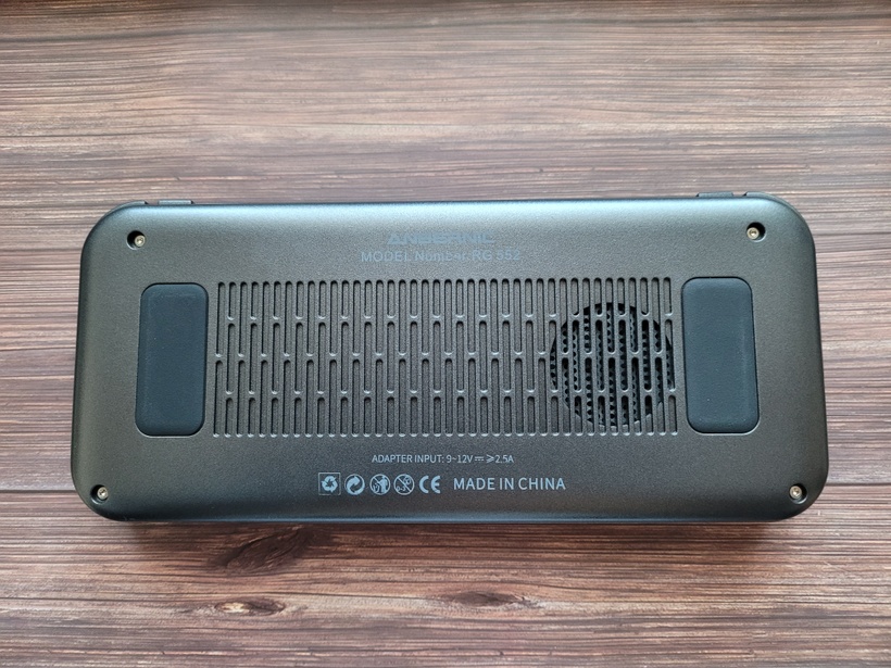
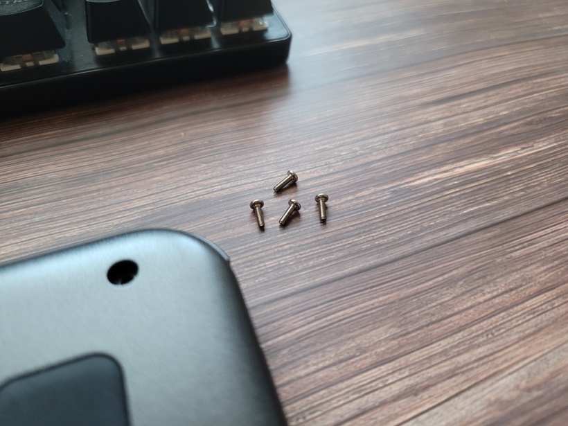
The backplate is held in place by 4 screws, which are easily removed with the right screwdriver bit.
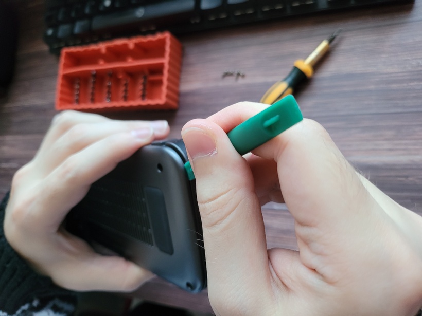
With the screws removed, use a guitar-pick or another plastic prying tool to unclip the back.
After the backplate has been unclipped, you should be able to flip it over to he left revealing the battery plug & cable.
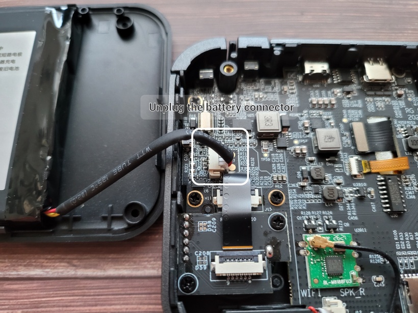
Which you will now carefully unplug.
The backplate will be out of the game for a while now, so put it somewhere safe for the time being, you will need the desk-space.
Desoldering the RTL8188FU WiFi module
Moving slightly downwards and right from the battery plug you will find the pre-installed RTL8188FU 2.4GHz WiFi module.
Unplug the RF antenna first.
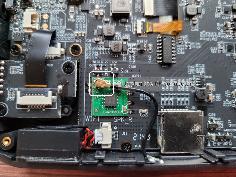
Now for the rough part that will scare most newcomers away... you will need to remove the old RTL8188FU chip from the PCB, which means you will have to unsolder the USB GND, Data+, Data-, VCC and Antenna + Antenna Ground pins before (carefully) removing the chip from the board.
Once you are done, clean the area and tin the pads to make the follow-up soldering easier.
When all is said and done, it should look something like this:

Getting ourselves a replacement RTL8821CU module
For this upgrade I will be using this RTL8821CU USB dongle as a base (because of its size & support for 3.3V operating voltage).
You can use another Realtek-based USB 2.0 dongle if you'd like, but make sure it will fit inside the RG552 interior and run off 3.3V, because that's all the internal USB pads give us.
Truth be told this more or less limits us to the RTL8821CU or the RTL8812CU as these are the only Realtek USB 2.0 devices I know that offer 2.4GHz, 5GHz and BT in one while still fitting the 3.3V envelope.
Which means if you want things to be easy, buy the same parts I used.
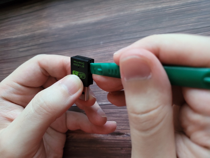
De-shelling the RTL8821CU USB module
Before we can do anything else we need to remove the module from its USB shell.
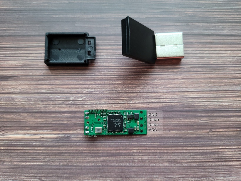
Which is easy if you bought the same one I did, as the case has a visible seamline that can be pried into allowing the whole thing to just fall apart into 3 pieces, one being the module we need.
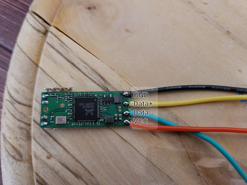
And here's a shot of the same module after its been pried open with the pins labeled accordingly.
Soldering the RTL8821CU module side up
Prepare 4 differently colored wires.
I went with red for VCC, blue for Data-, yellow for Data+ and black for GND.
These wires need to be soldered to the RTL8821CU module as shown below.
Soldering the PCB side & cable management
Rather than describing everything in detail beforehand, let's look at the final result and work our way backwards describing the steps necessary to get there.
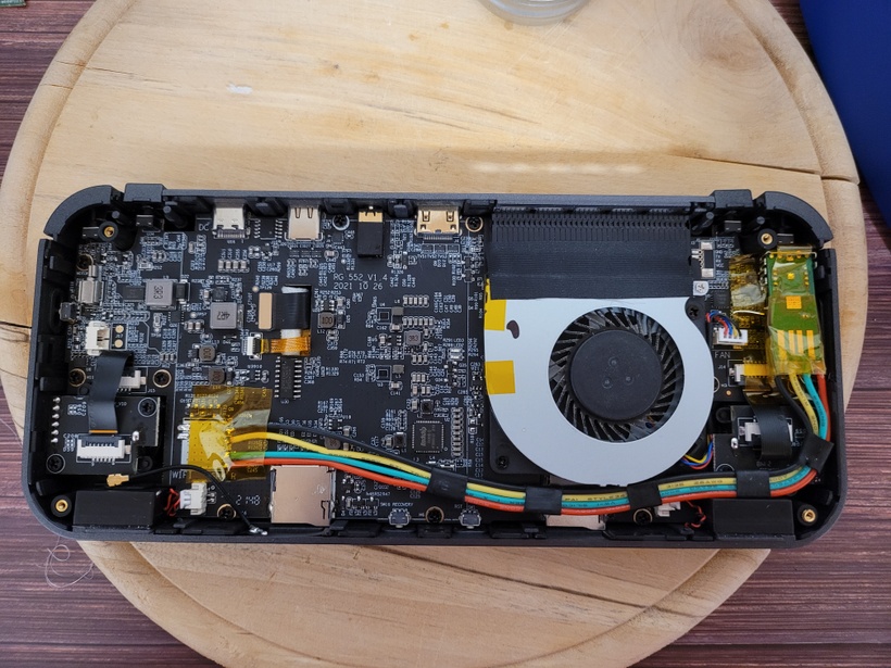
At this point it should be clear why I told you to color-code your cables.
All we have to do at this point is match up the GND, Data+, Data- and VCC pins of the internal USB port with those of the new RTL8821CU module.
Due to the rather hefty battery in this device we don't have a lot of clearance to work with, which means we need to keep these as flat as possible.
To make sure the wires don't go everywhere I used some cable shrink to flatten them into a bendable ribbon cable of sorts, making sure the cables run next to each other rather than on top of each other.
The replacement module is bigger than the RTL8188FU that came preinstalled, so I nestled it into the open gap between the L1/L2 shoulder and volume buttons (where it fits perfectly).
Make sure to use electrical tape where necessary to prevent shorting.
Better use too much than too little, but make sure not to cover the module's antennas!
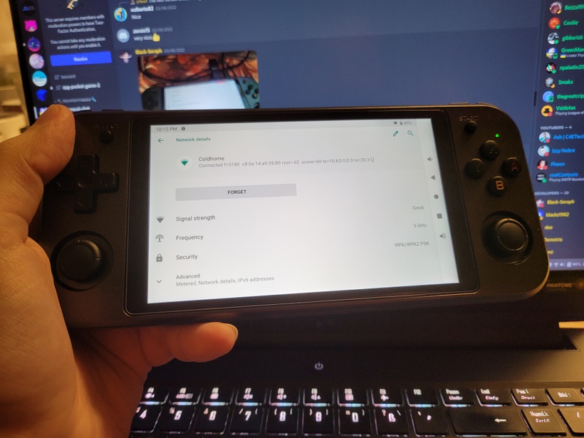
Reaping the benefits
Now all you have to do is plug the battery connector back in, clip the backplate back on and screw the 4 previously removed screws back in.
You're all done!
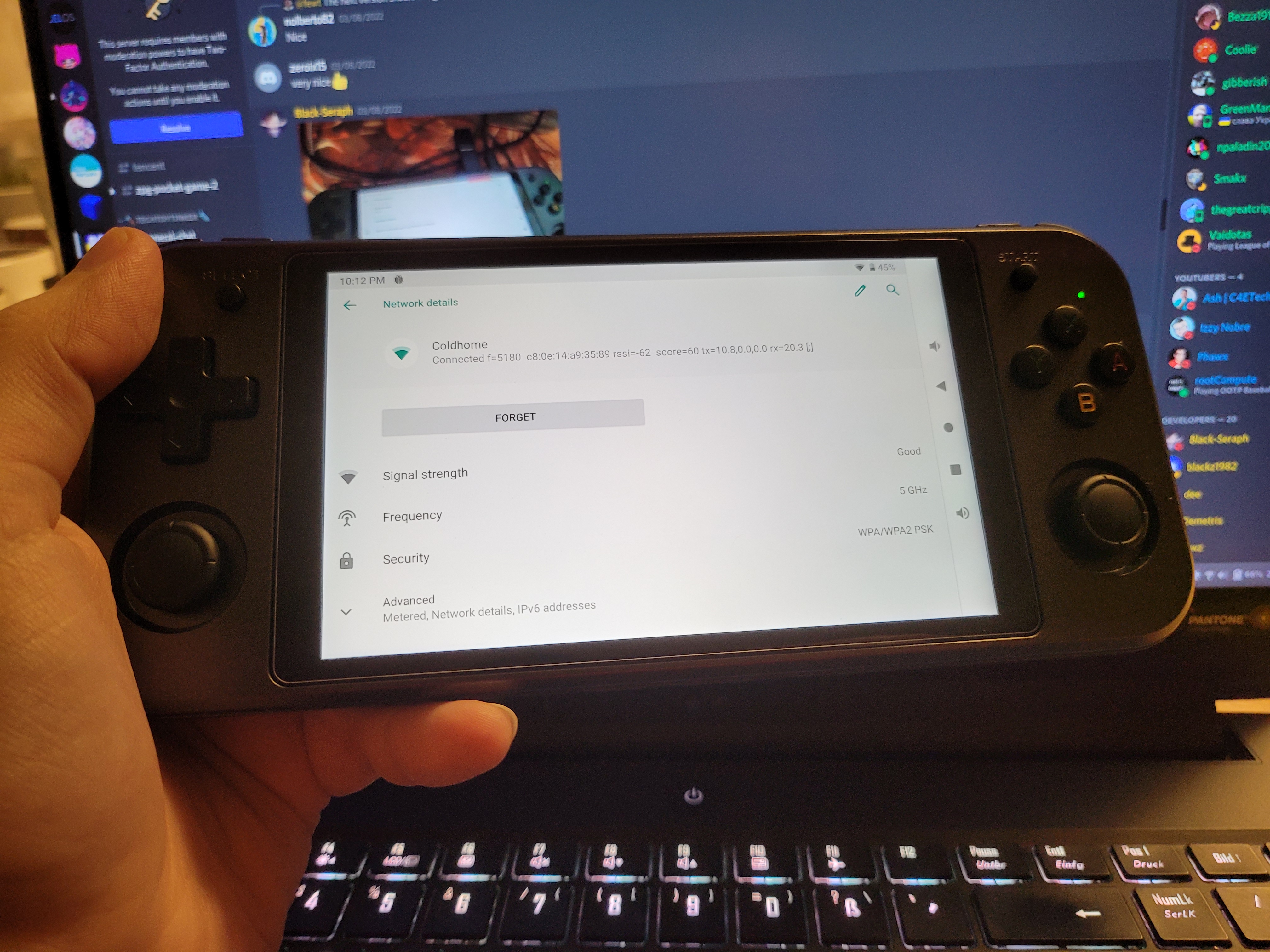
Enjoy your improved RG552, with 5GHz WiFi & Bluetooth 4.2 support!
Files